Memory Tetris: DRAM as a Tensor Cache over NVMe
CKE can potentially exploit known tensor lifetimes to manage a fixed DRAM working window over a much larger model stored on NVMe. This is explicit storage-tier scheduling, not an SSD pretending to be RAM.
Memory Tetris is not implemented in the production runtime. Hardware measurements and numerical certification are pending. This HTML page is the canonical public design and visual reference. Any lower-level Markdown implementation note must link back here and may not supersede this page. Nothing here is a supported feature, a measured speedup, or a committed model-compatibility claim.
What it is
- A lifetime-aware reuse policy for a fixed DRAM arena: when a tensor reaches its declared last use, its slot may become the final destination for a future tensor loaded asynchronously from NVMe (and, later, from another node).
- Explicit storage-tier scheduling: CKE owns slot lifetime, prefetch timing, transfer completion and consumption ordering.
- A planner that may manage a predictable DRAM working window more effectively than demand paging, because tensor lifetimes are known in advance.
What it is not
- Not SSD-backed virtual memory. This design does not claim that an SSD has DRAM latency or bandwidth, and it is not swap or page-cache demand paging with a new name.
- Not a promise that PCIe bandwidth equals application throughput. Nominal device numbers do not fix an incorrect schedule, insufficient look-ahead, small random reads or excessive copies.
- Not implemented. No production code path does this today; hardware gates decide whether the idea earns promotion.
The Mental Model
Three roles, kept deliberately separate:
DRAM = explicitly managed tensor working set
NVMe = capacity-oriented backing tier
CKE  = planner that schedules ownership, transfer and consumption
DRAM holds the fast working set — the tensors the current and next few computation steps touch. NVMe holds the capacity-oriented backing tier — the rest of the converted model, larger than the DRAM window. CKE sits between them and owns four things explicitly: slot lifetime (when an arena region is proven dead), prefetch (when a transfer starts), transfer completion (the event consumers wait on) and consumption (which kernel may run, and only after residency is verified). Dead arena regions are reused in place; live tensors are never shifted to make room.
Arena-Slot Reuse
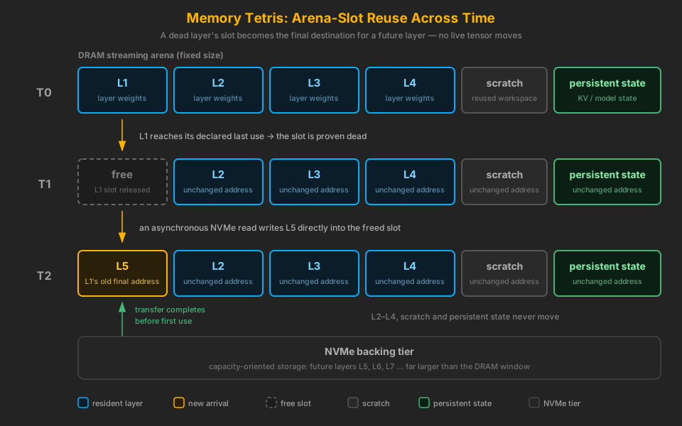
Assume four layer-weight groups fit in the streaming arena. When L1 completes and its slot
is proven dead, an asynchronous read may place L5 directly into that slot — at
L1's old final address. L2, L3, L4, scratch and
persistent state keep their addresses across the whole sequence. The planner changes slot ownership and
waits for the transfer-completion event before allowing the L5 consumer to run.
Overlapping Compute and I/O
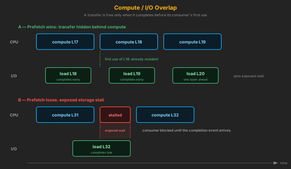
Storage traffic is hidden only when the next tensor arrives before its first use. With double buffering,
the desired timeline has the CPU computing L17, L18, L19 while the
I/O path loads L18, L19, L20 one layer ahead. Four outcomes matter
and must be distinguishable in telemetry: transfer hidden behind compute; exposed storage stall; transfer
completed before first use; consumer blocked because completion was late.
The exposure equation
“Hidden vs exposed” is one equation, and it is the same equation the CKE Constraint Model applies to every tier — DRAM prefetch, network synchronization and NVMe alike:
\[ T_{\text{exposed transfer}} = \max\!\left( 0,\ T_{\text{transfer}} - T_{\text{overlap window}} \right) \]A 250 µs NVMe prefetch beneath 300 µs of compute contributes zero exposed storage time; a 500 µs transfer beneath the same compute exposes 200 µs of stall. Memory Tetris's residency choices exist to drive this term to zero: grow the overlap window (look-ahead, double/triple buffering) or shrink the transfer (quantized artifacts, resident hot tensors), whichever the measured constraint rewards.
Bandwidth arithmetic without overstating it
For a 500 MB tensor, an idealized transfer takes about 71 ms at 7 GB/s and about 36 ms at 14 GB/s. These are division-based examples — bytes divided by nominal bandwidth — not measured end-to-end latency and not a performance guarantee.
| Example | Arithmetic | Idealized time | Nature |
|---|---|---|---|
| 500 MB tensor at 7 GB/s | 500 MB ÷ 7 GB/s | ≈ 71 ms | division-based illustration |
| 500 MB tensor at 14 GB/s | 500 MB ÷ 14 GB/s | ≈ 36 ms | division-based illustration |
Real throughput is shaped by latency, queue depth, filesystem behavior, thermal state, page-cache state, alignment and intermediate copies. A nominal 14 GB/s-class device cannot fix an incorrect schedule, insufficient look-ahead, small random reads or excessive copies — which is why Gen5 hardware is only worth evaluating after Gen4 proves the implementation can actually overlap I/O.
Actual Linux I/O Paths
An ordinary buffered read() does not guarantee direct PCIe DMA into the
final userspace arena; the kernel page cache and an additional copy may be involved. Four candidate
mechanisms must be measured independently, and no path earns provider promotion before benchmarking:
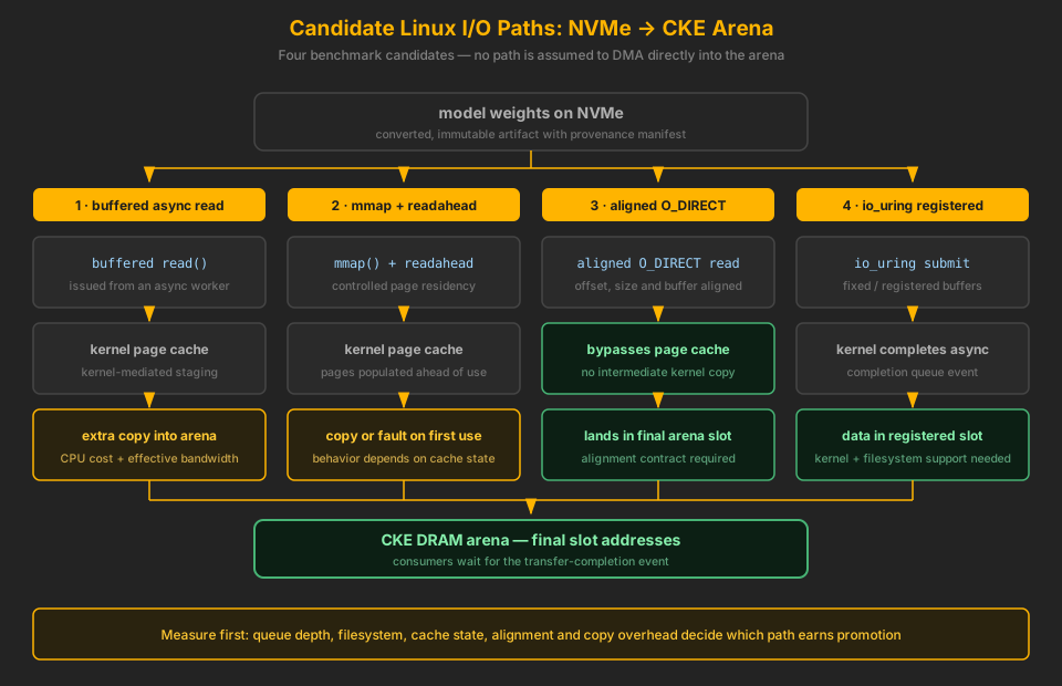
- Buffered asynchronous reads — simple and portable, but the kernel page cache plus a copy into the arena costs CPU and effective bandwidth.
mmap()plus controlled readahead — page residency is steered ahead of use, but behavior depends on cache state and a copy or fault still happens at first use.- Aligned
O_DIRECTreads — bypass the page cache and can land in final arena slots, subject to a strict alignment contract. - Registered
io_uringbuffers — asynchronous completion events into fixed buffers, where the kernel and filesystem support them.
The fastest mechanism is not assumed in advance. The planner interface should describe a transfer source and a completion event without hard-coding one Linux I/O mechanism into model circuits, so the winning path can be selected by measurement rather than by guesswork.
Dense and MoE Residency Policies
Dense: a predictable sliding window
Dense models provide a predictable layer sliding window with deterministic look-ahead: prefetch future layer weights in circuit order and retain only the number of layers allowed by the DRAM budget. This is the initial implementation target precisely because the schedule is known before execution starts.
MoE: a cache policy plus look-ahead
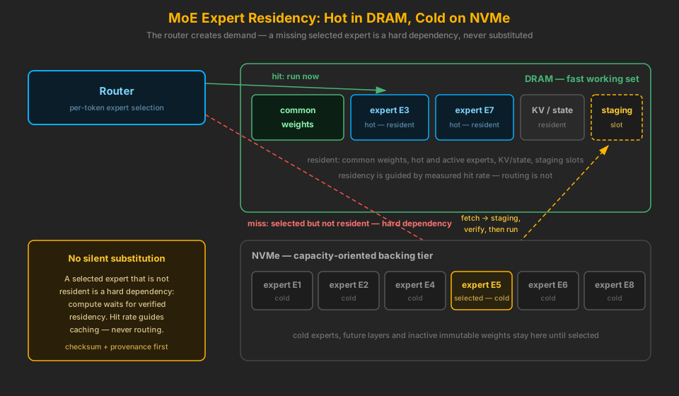
MoE models keep common weights and hot experts resident in DRAM while cold experts, future layers and inactive immutable weights stay on NVMe. Routing decisions determine immediate expert demand, and a selected expert that is not resident is a hard dependency: compute must wait for verified residency. Historical hit rate can guide residency, but no expert may be silently substituted — a cache never changes the arithmetic contract.
Safety Contracts: Fail Closed
Every tier-managed tensor carries machine-readable metadata: tensor id, source artifact and offset, arena slot and final address offset, size and alignment, first and last use, mutability and dirty state, storage tier and residency state, prefetch deadline and completion event, reuse distance, and checksum or artifact provenance. The planner must fail closed — refuse the schedule — when any of these hold:
- the previous slot owner is still live;
- a read or writable alias remains active;
- the slot is pinned by a kernel or an in-flight transfer;
- a writeback is pending for mutable state;
- the new transfer is incomplete at the consumer dependency;
- the source extent, destination extent or alignment is invalid;
- model provenance or checksum does not match the converted-model manifest;
- numerical execution would select a different arithmetic contract merely because the tensor came from another tier.
Immutable weights first
The first implementation target is converted, immutable weights, because they never need writeback. KV caches, recurrent state, gradients and optimizer state are explicitly out of scope for the first stages: they require later, explicit writeback, persistence and coherence contracts before they may be tier-managed.
X-Ray Evidence
The feature is not successful merely because a larger model runs. The proposed X-Ray integration records, per tensor and per layer, the full transfer lifecycle — request, first byte, completion and first use — so that hidden transfer, exposed wait and bandwidth are measured facts rather than hope. This extends the existing X-Ray evidence system (schema-validated reports, capture neutrality, fix ownership) from numerical parity to storage-tier transfers.
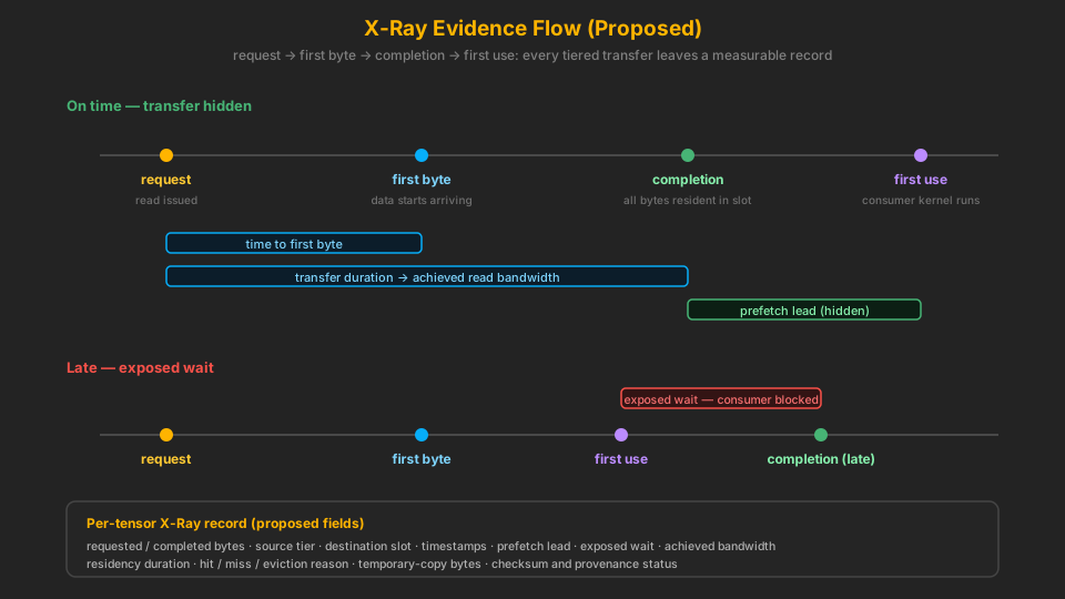
Proposed per-tensor report fields
- requested bytes and completed bytes;
- source tier and destination slot;
- request, first-byte, completion and first-use timestamps;
- prefetch lead time;
- exposed wait at first use;
- achieved read bandwidth;
- slot reuse and residency duration;
- cache hit, miss and eviction reason;
- temporary-copy bytes;
- checksum / provenance result.
Proposed aggregate report
- model bytes resident in DRAM;
- model bytes served by NVMe per token or prompt;
- I/O time hidden behind compute;
- exposed storage stall time;
- useful bandwidth versus device baseline;
- hot-expert hit rate for MoE;
- page-cache and direct-I/O mode;
- token parity against the fully resident baseline.
Numerical certification compares the tiered runtime against the same generated runtime and provider schedule with fully resident weights. Token parity alone is insufficient: selected layer and checkpoint outputs and artifact hashes must also match under their existing numerical contracts.
Hardware Results: Not Yet Certified
The table below is the planned evidence matrix. Every result cell is not yet certified: no reproducible Gen4 experiment has been run and recorded to CKE's evidence standard. A provisional Gen4 NVMe measurement exists in the lab but is deliberately withheld from this page until the command, artifact size and cache state are recorded — an unrecorded number is not a CKE benchmark.
| Experiment | Configuration | Result | Status |
|---|---|---|---|
| Device qualification | Gen4 NVMe sequential read, multiple block sizes and queue depths, direct and buffered | — | Not yet certified |
| Cache-state behavior | cold-cache and warm-cache measured separately | — | Not yet certified |
| Sustained reads | beyond the SSD SLC cache, with thermal and latency distributions recorded | — | Not yet certified |
| Synchronous baseline | fully resident versus one-slot synchronous streaming | — | Not yet certified |
| Buffering depth | one-slot versus double- and triple-buffered asynchronous streaming | — | Not yet certified |
| Tensor-size sweep | 64 MB through 1 GB layer sizes | — | Not yet certified |
| Overlap windows | compute windows shorter than, equal to and longer than transfer time | — | Not yet certified |
| Numerical parity | fully resident versus tiered, identical outputs | — | Not yet certified |
| Failure injection | forced short read, stale artifact, checksum failure, slot overlap | — | Not yet certified |
| Thread-count checks | identical output with 1, 8 and production thread counts | — | Not yet certified |
| MoE certification | dense model first, then a public MoE model with controlled routing | — | Not yet certified |
Every run must record the exact CPU, memory, filesystem, mount options, SSD firmware, temperature and free-space state. Gen5-class hardware is evaluated only after Gen4 establishes that the implementation can overlap I/O at all.
Distributed Extensibility
The transfer abstraction is designed so that a source can eventually be local DRAM, local NVMe, recomputation, or another CKE node. The planner can then compare resident reuse, local NVMe transfer, recomputation and network transfer without encoding distributed behavior into individual kernels. Distributed tensor loading is not implemented — this is an interface requirement for later stages, not a current capability. The Distributed CPU: Zip Fusion research design builds on this transfer abstraction: residency choices across nodes become a scheduling dimension for distributed execution.
Implementation Stages and Promotion Criteria
Planned stages
- Add immutable tensor source extents and storage-tier metadata to the model manifest and validated IR.
- Add a fixed, aligned streaming-slot allocator alongside persistent and scratch arena classes.
- Implement synchronous final-slot reads as the correctness baseline.
- Add asynchronous prefetch and explicit completion dependencies.
- Certify deterministic dense-layer sliding windows with one and two slots.
- Add double/triple buffering and tune look-ahead from measured kernel time.
- Add X-Ray transfer and stall reporting.
- Add MoE expert residency with deterministic cache-policy fixtures.
- Add mutable-state tiers only after explicit writeback and recovery design.
- Generalize the transfer source to remote-node tensors for distributed execution.
Promotion criteria
- No undeclared staging copy.
- No read from an incomplete or stale slot.
- The fully resident numerical contract remains unchanged.
- X-Ray accounts for all tiered bytes and exposed wait.
- Asynchronous mode beats the synchronous baseline reproducibly.
- The selected model exceeds available DRAM or demonstrates a measured residency benefit — otherwise storage streaming adds complexity without value.
The defensible claim
CKE's explicit tensor lifetimes may let it manage a predictable DRAM working window more effectively than demand paging. The hardware gates — not the diagrams — determine how much I/O can actually be hidden.
Related Pages
- The CKE Constraint Model — the shared math this page's exposure equation belongs to
- Deterministic Memory — compile-time known offsets that make slot lifetimes auditable
- Distributed CPU: Zip Fusion — the distributed-execution research design that treats residency as a scheduling dimension
- Memory Safety — bump allocator, canaries and arena discipline
- Memory Reality — honest memory-capacity accounting for large models
- Scaling Philosophy — the CPU-only, Linux-first hardware bet behind this research
- Research Tracker — other proposed techniques and their status